Topology Guide
Slurm can be configured to support topology-aware resource
allocation to optimize job performance.
Slurmは、トポロジ対応のリソース割り当てをサポートするように構成して、ジョブのパフォーマンスを最適化できます。
Slurm supports several modes of operation, one to optimize performance on
systems with a three-dimensional torus interconnect and another for
a hierarchical interconnect.
Slurmは、いくつかの操作モードをサポートしています。1つは、3次元トーラス相互接続を備えたシステムのパフォーマンスを最適化するためのもので、もう1つは階層的相互接続のためのものです。
The hierarchical mode of operation supports both fat-tree or dragonfly networks,
using slightly different algorithms.
階層動作モードは、わずかに異なるアルゴリズムを使用して、ファットツリーネットワークとトンボネットワークの両方をサポートします。
Slurm's native mode of resource selection is to consider the nodes
as a one-dimensional array.
Slurmのリソース選択のネイティブモードは、ノードを1次元配列と見なすことです。
Jobs are allocated resources on a best-fit basis.
ジョブには、最適な方法でリソースが割り当てられます。
For larger jobs, this minimizes the number of sets of consecutive nodes
allocated to the job.
大規模なジョブの場合、これにより、ジョブに割り当てられる連続ノードのセットの数が最小限に抑えられます。
Three-dimension Topology
Some larger computers rely upon a three-dimensional torus interconnect.
一部の大型コンピューターは、3次元トーラス相互接続に依存しています。
The Cray XT and XE systems also have three-dimensional
torus interconnects, but do not require that jobs execute in adjacent nodes.
Cray XTおよびXEシステムにも3次元トーラス相互接続がありますが、隣接するノードでジョブを実行する必要はありません。
On those systems, Slurm only needs to allocate resources to a job which
are nearby on the network.
これらのシステムでは、Slurmはネットワーク上で近くにあるジョブにリソースを割り当てるだけで済みます。
Slurm accomplishes this using a
Hilbert curve
to map the nodes from a three-dimensional space into a one-dimensional
space.
Slurmは、ヒルベルト曲線を使用してノードを3次元空間から1次元空間にマッピングすることでこれを実現します。
Slurm's native best-fit algorithm is thus able to achieve a high degree
of locality for jobs.
したがって、Slurmのネイティブの最適なアルゴリズムは、ジョブの高度な局所性を実現できます。
Hierarchical Networks
Slurm can also be configured to allocate resources to jobs on a
hierarchical network to minimize network contention.
Slurmは、ネットワークの競合を最小限に抑えるために、階層ネットワーク上のジョブにリソースを割り当てるように構成することもできます。
The basic algorithm is to identify the lowest level switch in the
hierarchy that can satisfy a job's request and then allocate resources
on its underlying leaf switches using a best-fit algorithm.
基本的なアルゴリズムは、ジョブの要求を満たすことができる階層内の最下位レベルのスイッチを識別し、最適なアルゴリズムを使用して、基になるリーフスイッチにリソースを割り当てることです。
Use of this logic requires a configuration setting of
TopologyPlugin=topology/tree.
このロジックを使用するには、TopologyPlugin = topology / treeの構成設定が必要です。
Note that slurm uses a best-fit algorithm on the currently
available resources.
slurmは、現在利用可能なリソースに最適なアルゴリズムを使用していることに注意してください。
This may result in an allocation with
more that the optimum number of switches.
これにより、最適な数を超えるスイッチが割り当てられる可能性があります。
The user can request
a maximum number of switches for the job as well as a
maximum time willing to wait for that number using the --switches
option with the salloc, sbatch and srun commands.
ユーザーは、salloc、sbatch、およびsrunコマンドで--switchesオプションを使用して、ジョブのスイッチの最大数と、その数を待機する最大時間を要求できます。
The parameters can
also be changed for pending jobs using the scontrol and squeue commands.
scontrolおよびsqueueコマンドを使用して、保留中のジョブのパラメーターを変更することもできます。
At some point in the future Slurm code may be provided to
gather network topology information directly.
将来のある時点で、ネットワークトポロジ情報を直接収集するためにSlurmコードが提供される可能性があります。
Now the network topology information must be included
in a topology.conf configuration file as shown in the
examples below.
次に、以下の例に示すように、ネットワークトポロジ情報をtopology.conf構成ファイルに含める必要があります。
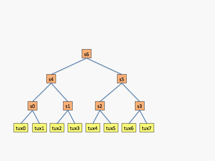
The first example describes a three level switch in which
each switch has two children.
最初の例は、各スイッチに2つの子がある3レベルスイッチについて説明しています。
Note that the SwitchName values are arbitrary and only
used to bookkeeping purposes, but a name must be specified on
each line.
SwitchNameの値は任意であり、簿記の目的でのみ使用されますが、各行に名前を指定する必要があることに注意してください。
The leaf switch descriptions contain a SwitchName field
plus a Nodes field to identify the nodes connected to the
switch.
リーフスイッチの説明には、SwitchNameフィールドと、スイッチに接続されているノードを識別するためのNodesフィールドが含まれています。
Higher-level switch descriptions contain a SwitchName field
plus a Switches field to identify the child switches.
上位レベルのスイッチの説明には、SwitchNameフィールドと、子スイッチを識別するためのSwitchesフィールドが含まれています。
Slurm's hostlist expression parser is used, so the node and switch
names need not be consecutive (e.g. "Nodes=tux[0-3,12,18-20]"
and "Switches=s[0-2,4-8,12]" will parse fine).
Slurmのホストリスト式パーサーが使用されるため、ノード名とスイッチ名は連続している必要はありません(例: "Nodes = tux [0-3,12,18-20]"および "Switches = s [0-2,4-8,12 ] "は正常に解析されます)。
An optional LinkSpeed option can be used to indicate the
relative performance of the link.
オプションのLinkSpeedオプションを使用して、リンクの相対的なパフォーマンスを示すことができます。
The units used are arbitrary and this information is currently not used.
使用される単位は任意であり、この情報は現在使用されていません。
It may be used in the future to optimize resource allocations.
将来的には、リソース割り当てを最適化するために使用される可能性があります。
The first example shows what a topology would look like for an
eight node cluster in which all switches have only two children as
shown in the diagram (not a very realistic configuration, but
useful for an example).
最初の例は、図に示すように、すべてのスイッチに2つの子しかない8ノードクラスターのトポロジがどのようになるかを示しています(あまり現実的な構成ではありませんが、例として役立ちます)。
# topology.conf
# Switch Configuration
SwitchName=s0 Nodes=tux[0-1]
SwitchName=s1 Nodes=tux[2-3]
SwitchName=s2 Nodes=tux[4-5]
SwitchName=s3 Nodes=tux[6-7]
SwitchName=s4 Switches=s[0-1]
SwitchName=s5 Switches=s[2-3]
SwitchName=s6 Switches=s[4-5]

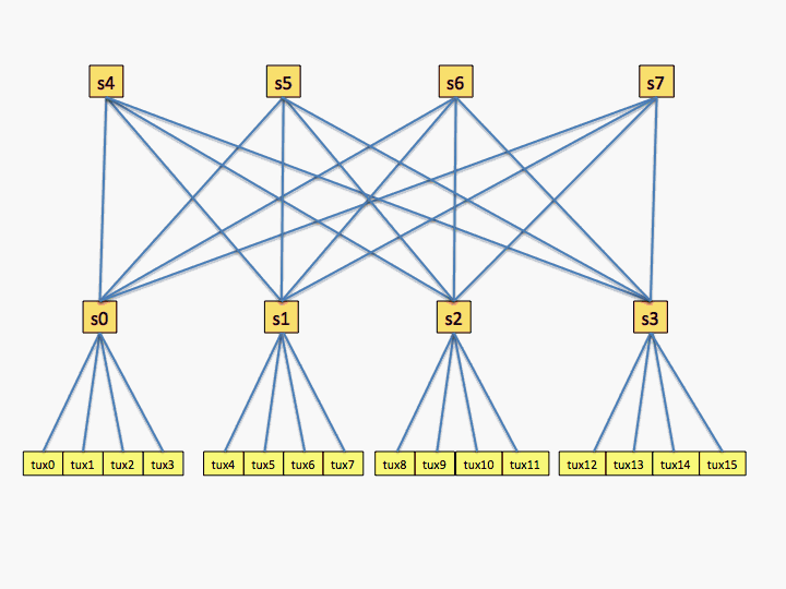
The next example is for a network with two levels and
each switch has four connections.
次の例は、2つのレベルがあり、各スイッチに4つの接続があるネットワークの場合です。
# topology.conf
# Switch Configuration
SwitchName=s0 Nodes=tux[0-3]   LinkSpeed=900
SwitchName=s1 Nodes=tux[4-7]   LinkSpeed=900
SwitchName=s2 Nodes=tux[8-11]  LinkSpeed=900
SwitchName=s3 Nodes=tux[12-15] LinkSpeed=1800
SwitchName=s4 Switches=s[0-3]  LinkSpeed=1800
SwitchName=s5 Switches=s[0-3]  LinkSpeed=1800
SwitchName=s6 Switches=s[0-3]  LinkSpeed=1800
SwitchName=s7 Switches=s[0-3]  LinkSpeed=1800

As a practical matter, listing every switch connection
definitely results in a slower scheduling algorithm for Slurm
to optimize job placement.
実際問題として、すべてのスイッチ接続を一覧表示すると、Slurmがジョブの配置を最適化するためのスケジューリングアルゴリズムが遅くなることは間違いありません。
The application performance may achieve little benefit from such optimization.
アプリケーションのパフォーマンスは、このような最適化からほとんどメリットが得られない場合があります。
Listing the leaf switches with their nodes plus one top level switch
should result in good performance for both applications and Slurm.
リーフスイッチとそのノードおよび1つのトップレベルスイッチを一覧表示すると、アプリケーションとSlurmの両方で良好なパフォーマンスが得られるはずです。
The previous example might be configured as follows:
前の例は、次のように構成されている可能性があります。
# topology.conf
# Switch Configuration
SwitchName=s0 Nodes=tux[0-3]
SwitchName=s1 Nodes=tux[4-7]
SwitchName=s2 Nodes=tux[8-11]
SwitchName=s3 Nodes=tux[12-15]
SwitchName=s4 Switches=s[0-3]
Note that compute nodes on switches that lack a common parent switch can
be used, but no job will span leaf switches without a common parent
(unless the TopologyParam=TopoOptional option is used).
共通の親スイッチがないスイッチの計算ノードを使用できますが、共通の親がないリーフスイッチにまたがるジョブはありません(TopologyParam = TopoOptionalオプションが使用されている場合を除く)。
For example, it is legal to remove the line "SwitchName=s4 Switches=s[0-3]"
from the above topology.conf file.
たとえば、上記のtopology.confファイルから「SwitchName = s4Switches = s [0-3]」という行を削除することは合法です。
In that case, no job will span more than four compute nodes on any single leaf
switch.
その場合、単一のリーフスイッチ上の4つを超える計算ノードにまたがるジョブはありません。
This configuration can be useful if one wants to schedule multiple physical
clusters as a single logical cluster under the control of a single slurmctld
daemon.
この構成は、単一のslurmctldデーモンの制御下で、複数の物理クラスターを単一の論理クラスターとしてスケジュールする場合に役立ちます。
For systems with a dragonfly network, configure Slurm with
TopologyPlugin=topology/tree plus TopologyParam=dragonfly.
トンボネットワークを備えたシステムの場合、TopologyPlugin = topology / treeとTopologyParam = dragonflyを使用してSlurmを構成します。
If a single job can not be entirely placed within a single network leaf
switch, the job will be spread across as many leaf switches as possible
in order to optimize the job's network bandwidth.
単一のジョブを単一のネットワークリーフスイッチ内に完全に配置できない場合、ジョブのネットワーク帯域幅を最適化するために、ジョブは可能な限り多くのリーフスイッチに分散されます。
NOTE:Slurm first identifies the network switches which provide the
best fit for pending jobs and then selects the nodes with the lowest "weight"
within those switches.
注:Slurmは、最初に保留中のジョブに最適なネットワークスイッチを特定し、次にそれらのスイッチ内で「重み」が最も低いノードを選択します。
If optimizing resource selection by node weight is more
important than optimizing network topology then do NOT use the
topology/tree plugin.
ネットワークトポロジの最適化よりもノードの重みによるリソース選択の最適化の方が重要な場合は、トポロジ/ツリープラグインを使用しないでください。
NOTE:The topology.conf file for an Infiniband switch can be
automatically generated using the slurmibtopology tool found here:
注:Infinibandスイッチのtopology.confファイルは、次の場所にあるslurmibtopologyツールを使用して自動的に生成できます。
https://ftp.fysik.dtu.dk/Slurm/slurmibtopology.sh.
NOTE:The topology.conf file for an Omni-Path (OPA) switch can
be automatically generated using the opa2slurm tool found here:
注:Omni-Path(OPA)スイッチのtopology.confファイルは、次の場所にあるopa2slurmツールを使用して自動的に生成できます。
https://gitlab.com/jtfrey/opa2slurm.
User Options
For use with the topology/tree plugin, user can also specify the maximum
number of leaf switches to be used for their job with the maximum time the
job should wait for this optimized configuration.
トポロジ/ツリープラグインで使用する場合、ユーザーは、ジョブに使用するリーフスイッチの最大数と、ジョブがこの最適化された構成を待機する最大時間を指定することもできます。
The syntax for this option
is "--switches=count[@time]".
このオプションの構文は「--switches = count [@time]」です。
The system administrator can limit the maximum time that any job can
wait for this optimized configuration using the SchedulerParameters
configuration parameter with the max_switch_wait option.
システム管理者は、max_switch_waitオプションを指定したSchedulerParameters構成パラメーターを使用して、この最適化された構成をジョブが待機できる最大時間を制限できます。
Environment Variables
If the topology/tree plugin is used, two environment variables will be set
to describe that job's network topology.
トポロジ/ツリープラグインを使用する場合、そのジョブのネットワークトポロジを記述するために2つの環境変数が設定されます。
Note that these environment variables
will contain different data for the tasks launched on each node.
これらの環境変数には、各ノードで起動されたタスクの異なるデータが含まれることに注意してください。
Use of these
environment variables is at the discretion of the user.
これらの環境変数の使用は、ユーザーの裁量に委ねられています。
SLURM_TOPOLOGY_ADDR:
The value will be set to the names network switches which may be involved in
the job's communications from the system's top level switch down to the leaf
switch and ending with node name.
SLURM_TOPOLOGY_ADDR:値は、システムのトップレベルスイッチからリーフスイッチまでのジョブの通信に関与し、ノード名で終わる可能性のあるネットワークスイッチの名前に設定されます。
A period is used to separate each hardware
component name.
ピリオドは、各ハードウェアコンポーネント名を区切るために使用されます。
SLURM_TOPOLOGY_ADDR_PATTERN:
This is set only if the system has the topology/tree plugin configured.
SLURM_TOPOLOGY_ADDR_PATTERN:これは、システムにトポロジー/ツリープラグインが構成されている場合にのみ設定されます。
The value will be set component types listed in SLURM_TOPOLOGY_ADDR.
値は、SLURM_TOPOLOGY_ADDRにリストされているコンポーネントタイプに設定されます。
Each component will be identified as either "switch" or "node".
各コンポーネントは、「スイッチ」または「ノード」として識別されます。
A period is used to separate each hardware component type.
ピリオドは、各ハードウェアコンポーネントタイプを区切るために使用されます。
Last modified 14 June 2018